Revit Adaptive Panels
Apr 11, 2022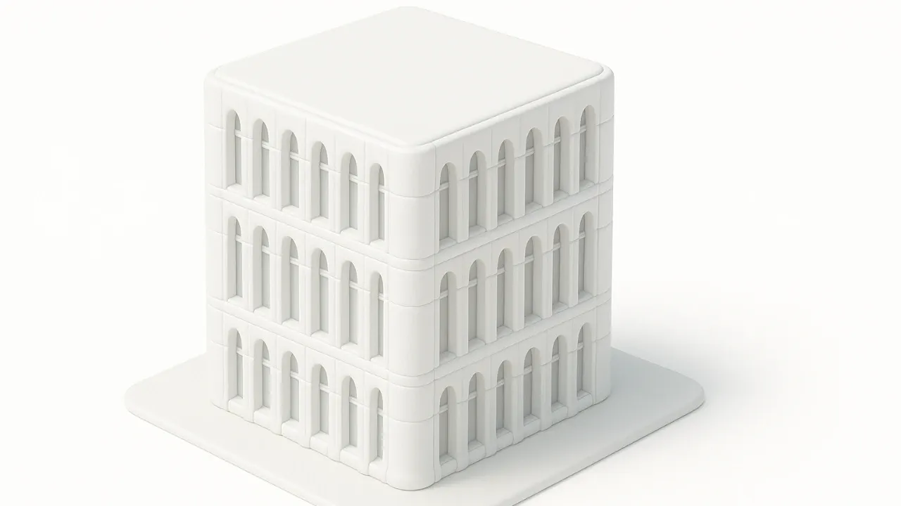
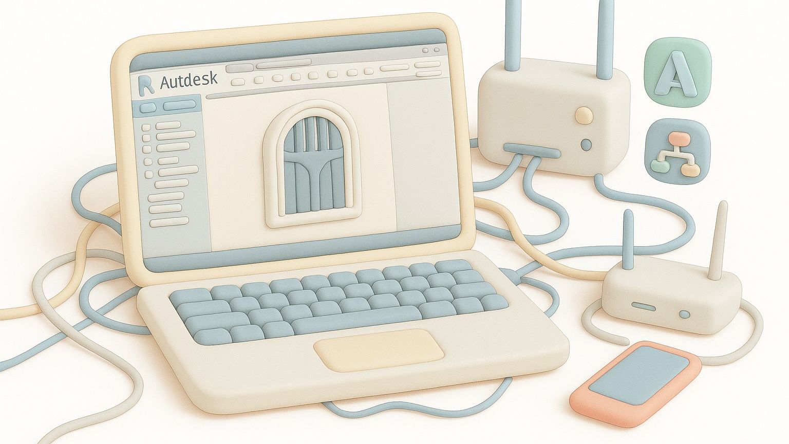
Revit Adaptive Panels: Design Flexible Facades with Ease
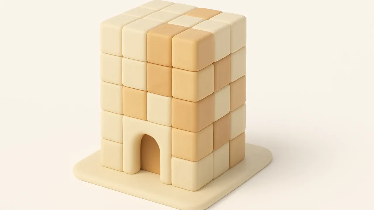
I found an exciting project while scrolling through my Instagram feed. As you know, I love using adaptive panels in Revit. I always try to use the standard set of tools available in Revit. And today’s post will be no exception. I will only use the out-of-the-box tools available to us. Below you will see a facade that I want to repeat.

The hardest thing in designing the facade of such a building is to correctly divide the facade «grid». Let’s first visually evaluate how we can separate the panels.
If we look closely, we will see that the panels are already separated, and we can only repeat this scheme. For example, take a look at the image below. We only have 2 types of panels. I would call them «Arched T» and «Flat» facade panels.


We have dealt with you regarding the division of building facade panels into types. Now it’s time for us to move into Revit and implement our idea in the program.
First, I want to make a reservation that we will not try to make the panel overly parameterized. Remember the golden rule:
“If you look for perfection, you’ll never be content — Leo Tolstoy
We will record some panel data as static parameters based on this quote.
The “Family”, based on which we will work — Pattern Based Family

We will set the size of the panels to approximately the following values. Height — 6000 mm and Width — 2600mm

I’ll refer back to the quote above again — “why I don’t use a 'fully' adaptive panel”.
Our task is to make it simple and functional. The choice of «Pattern-Based Family» is rationally based on the tasks that we are currently facing.
A feature of the construction of any adoptive family is that we use construction by points. The construction by points has some peculiarities. Here are the main ones:
- Each point has its own work planes
- Each point can move in space independently of the other
- Each point has its own coordinate system
Stage one. Creating
We will start the construction by placing a point on the reference line. Note that the reference lines already exist and can’t be deleted.

The parameters that are responsible for the location of points on the reference line are «Normalized Curve». As I mentioned earlier, this parameter places a point on the line and uses length instead of a parameter. That divides the length of the line from 0 to 1.

We will change Normalized to Segment Length. This will allow us to indicate the actual dimensions. For example, above you can see that the distance is indicated as 0.63, but once we change the type, the length will be 3824 mm

You probably noticed that «some blue field» is present around the point. This blue halo around the point is the point’s work plane. We will build on them the rest of the «dependent» points

We get 3 levels of the point. In fact, there may be many times more of them, but the structure will be the same.

Points that have dependencies can be controlled by the points they depend on. That is, if you look at the picture above, you will see 3 levels of points. If we change the position of point 2, point 3 will certainly follow point 2. Below is an example:

I talk more about dependencies in my video. Here I want to draw your attention to the important points in the construction of adaptive panels.
The main problem is when the point «confuses» the coordinates we need. For example, we need the distance from the point to be 500 mm upwards from it. Pay attention to the picture below:

We need to fix the hosted point in order to fix the position of the point in space, as shown below:

Geometry
Building geometry for adaptive families is very similar to how we work with families in context. I will only note that I strongly recommend using Reference line instead of regular lines to build geometry. This is due to the fact that if you suddenly delete the geometry, the line will not go anywhere. It’s comfortable.

Geometry can be built in «pieces». We can visually divide the panels into «pieces». For example, we can choose not a closed profile, but 2 lines, and create a plane between them. This option is working. I still prefer to use closed profiles, as it reduces the chance of getting «surprises». Also, the method of working with closed profiles allows you to create a plane of any complexity.

Conclusion
In conclusion, I want to say that the use of adaptive panels in Revit completely covers the need for facade modeling. The only difficulty that you may encounter is that this tool can only show results with proper skill. You need to approach the issue of creation already at the task stage. You need to understand how panels will be placed and what parameters will affect them. You need to do a lot of work before you start creating.
You can achieve great results already when using a bunch of adaptive panels and Dynamo, but this topic is for a completely different article.
Below you will find a video tutorial on these panels, where I dwelt on their creation in great detail.

Thank you.
Niko G.